GPR Surveys of Road Pavements
Industry leading GPR technology
A ZeticaRoad GPR survey will incorporate a dense array, continuous wave stepped frequency 3D GPR system from 3D-Radar. The latest version of the Design Manual for Roads and Bridges, also known as CS 229, promotes the use of 3D GPR as it can improve the quality of data or improve the productivity and/or coverage of a survey without reducing accuracy and reliability when reporting many pavement features, even at traffic-speed.
The continuous wave stepped frequency (CWSF) GPR system can utilise either air coupled or ground coupled antenna arrays both of which operate over a frequency range of 200 MHz – 3 GHz and consist of separate, transversely arranged antenna elements providing measurements at 75mm across the road. However, in our experience the method of coupling effects the data meaning the air coupled is optimal for layer thickness measurement and being a wider array, is optimal for rapid coverage. The ground coupled antenna is optimal for defect detection but can be used for layer thickness mapping and vice versa. We will deploy the correct antenna for survey based on priorities but we can also deploy both if required.
Multiple passes with the antenna can be combined to provide full-lane width or even carriageway width data meaning defects are always within coverage. This is enabled by the high positional accuracy provided by our vehicle’s onboard GPS and inertial navigation systems.
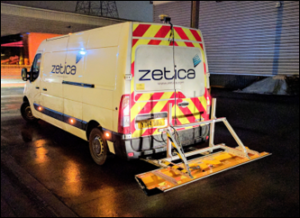
3D CWSF air coupled antenna deployment
- Optimum for traffic-speed surveys where layer thickness measurement is priority.
- 29 measurement channels over 2.2m meaning rapid, efficient coverage.
- 75mm across-road measurement spacing
- Along-road measurement spacing is configurable based on the required maximum survey speed.
- >1m depth penetration in most conditions.
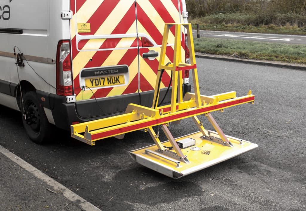
3D CWSF ground coupled antenna deployment
- Optimum for surveys where localised defect or buried object mapping is priority.
- 12 measurement channels over 0.8m.
- 75mm across-road measurement spacing
- Along-road measurement spacing is configurable based on the required maximum survey speed.
- >1.5m depth penetration in most conditions.
What pavement features can GPR detect
| Detectable Pavement Features in Accordance with CS 229 | Recommended Survey Type | Optimum Antenna Deployment | Comment |
|---|---|---|---|
| Construction changes | Traffic Speed | 3D CWSF air coupled* | |
| Bound and unbound layer thicknesses and profiles | Traffic Speed | 3D CWSF air coupled* | |
| Identification of buried structural features such as concrete joints, or concrete beams | Traffic Speed | 3D CWSF ground coupled | |
| Large air-filled voids directly beneath unreinforced concrete slabs | Traffic Speed | 3D CWSF air coupled* | |
| Water-filled voids directly beneath unreinforced concrete slabs | Traffic Speed | 3D CWSF air coupled* | |
| Depth and gross misalignment of joint dowel bars; detail of steel reinforcement in concrete slabs | Slow speed | 3D CWSF ground coupled | May be optimum to carry out on foot with a handheld system depending on the size of the area and other factors. |
| Variation of sub-base moisture content | Traffic Speed | 3D CWSF air coupled* | |
| Depths of surface cracks in fully flexible pavements | Slow speed | High frequency UWB | GPR can identify areas where cracking is present but depth measurement is unreliable |
| Identification of broad types of pavement materials | Traffic Speed | 3D CWSF air coupled | This is not always possible without cores regardless of the GPR system used. |
| Debonding of pavement layers | Traffic Speed | 3D CWSF air coupled* | |
| Condition of steel in concrete | Slow speed | 3D CWSF ground coupled | We do not recommend that GPR is used in isolation for this feature. |
| Voids and wet patches beneath reinforced concrete slabs | Slow speed | 3D CWSF ground coupled | |
| Small voids directly beneath unreinforced concrete slabs | Slow speed | 3D CWSF ground coupled | |
| Debonding of joint sealant | Slow speed | 3D CWSF ground coupled |
* 3D CWSF ground coupled antenna will also provide data which can be used for mapping these features, however, the increased coverage/efficiency provided by the air coupled antenna means that this is considered optimum.
Know your limits
The above table is presented as a useful guide for choosing a GPR system for a particular survey. However, selecting a single system or antenna for a survey will always a compromise between speed, coverage, resolution and depth penetration. There are cases where complimentary detail is required to maximise the effectiveness of a survey. For example mapping thin surface layers, tie and dowel bars, cement bound, and deeper unbound layers in combination will not be optimal using one type of GPR system alone. Zetica has extensive experience combining continuous wave and UWB GPR systems where complementary detail is required in a single pass.
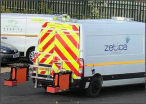
Ultrawideband GPR system installed on survey vehicle
Case Study
Coming soon…
Keen to find out more?
To discuss road surveys with one of our experts or to get an estimate for our services, please call (0)1993 886 682, email roads@zetica.com or contact us online.